
Flexible PCBs for High-Temperature
A flexible printed circuit board’s design and materials will determine whether it can function in a high-temperature environment. The PCB’s copper traces and solder mask must be able to withstand the ambient temperature in which it will operate, as well as the temperatures that are required for soldering and reflow processes. Additionally, the flex pcbs must be able to accommodate thermal expansion without impacting its structural stability or electrical connections. The answer to this question depends on the application and the environment, but through careful material selection, proper construction techniques and design considerations, a flexible circuit board can be used in harsh environments.
Flexible PCBs can be manufactured with different layers and surface finishes. The layer count and the type of surface finish will affect the cost of a flex PCB. Selective plating, for example, requires more time, labor and materials than non-selective plating. This will increase the cost of a flex circuit board. In addition, multiple surface finishes such as tin and gold are typically more expensive than standard finishes.
In order to reduce the cost of a flex circuit, the number of layers can be reduced and the materials used can be selected carefully. For example, the use of acrylic adhesives instead of epoxy adhesives can reduce costs. Similarly, the choice of a polyimide (PI) base raw material can decrease the cost. PI is an adhesiveless base that does not require an additional layer of adhesive to attach the flex and rigid sections together, making it an efficient option for a hybrid flex-rigid-circuit design.
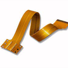
Flexible PCBs for High-Temperature Environments
When designing a flex-rigid-circuit, the location of the flex section should be considered. Putting the flex layer inside of the rigid portion of the board will decrease the amount of stress on the flexible materials and improve the impedance of signal transmission. However, if the flex layer will be exposed to the outer layers of the board, it should be laminated with an adhesive to protect it from damage.
The flex-rigid-circuit structure can be further optimized by using stiffeners to support mounting components and provide mechanical strength. These can also be made of a rigid material such as kapton or FR4. Stiffeners will increase the thickness and rigidity of a flex-rigid-circuit, which will make it less susceptible to movement and vibration.
A flex-rigid-circuit’s performance is also determined by the layer-to-plate and drill-to-copper distances. It is important to ensure the drilled holes in a flex-rigid-circuit are spaced far enough apart to avoid signal loss due to bending. This can be accomplished by having a minimum drill-to-copper distance of 8 mil. A flex-rigid-circuit can also be made more reliable by using a pad-only-plating process. This technique will provide consistent copper thickness, width and spacing for conductor traces and will help to reduce signals errors caused by flex-material movement or contraction. This will also improve etch yields for small etch patterns and control impedance in high-speed applications.